
![[Top]](../../images/home.jpg)
![[Contents]](../../images/contents.jpg)
![[Prev]](../../images/previous.jpg)
![[Next]](../../images/next.jpg)
![[Last]](../../images/index.jpg)


Setting Up and Testing the MAX Hardware
This chapter covers these topics:
Planning the hardware installation
This section explains what you need before you install the MAX hardware.
What you need before you start
Before you install the MAX, make sure have these items:
Guidelines for installing digital modems
- The Series56 architecture requires that all modem modules within a MAX chassis be homogeneous. That is, Series56 modules may not be mixed with non-Series56 digital modem modules.
- The Series56 architecture also requires that the modem density be homogeneous. Modem modules with mixed densities (for example, 8-port and 12-port modem modules) cannot be combined in a single chassis.
- The MAX can support a total of 72 digital modems.
Guidelines for installing MAX units in a rack
This section provides installation guidelines for installing MAX units in a rack. Figure 2-1 illustrates an example installation.
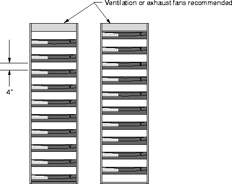
Figure 2-1. Installing MAX units in a rack.
If you ordered MAX expansion cards separately, continue with the next section. If all of your expansion cards are preinstalled, skip to the section Setting up the hardware.
Inserting an expansion card
 Warning: When installing any equipment, make sure to use proper procedures for static
electricity, such as using a grounding mat and a wrist strap.
If your MAX package includes expansion modules that are not already installed in your MAX, insert the modules now. Follow these steps:
- Make sure the MAX power is off and the power cord is unplugged.
Warning: Failure to turn off the MAX power and unplug the power cord could result in
injury to you.
Hold the expansion card with the network ports facing you and insert the card into a back
panel slot as shown in Figure 2-2. Do not grab the slot cards from both ends. Make sure
you insert the card into the guides within the same plane.
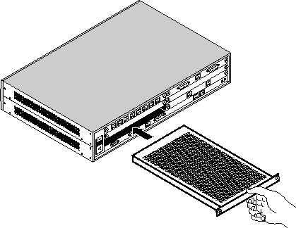
Figure 2-2. Inserting an expansion card into a MAX slot
- Push the card along the internal guides until the it is secure. The face plate of the
expansion card should touch the back panel of the MAX.
Caution: Do not force the expansion card into the slot. Doing so can damage the card or
slot connector.
Tighten the screws on either side of the module as shown in the following figure.
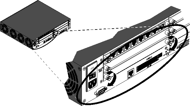
Figure 2-3. Tightening slot card thumbscrews
Now you are ready to set up the hardware.
Setting up the hardware
Before you set up the MAX hardware, you need to make sure you have the appropriate space. You can install the MAX in a 19-inch or 23-inch rack.
The following illustrations show the dimensions of both base MAX units-the single power supply unit and the redundant power supply unit.
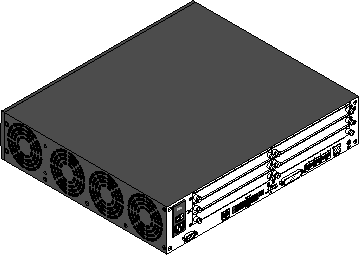
Figure 2-4. Dimensions of the single power supply unit
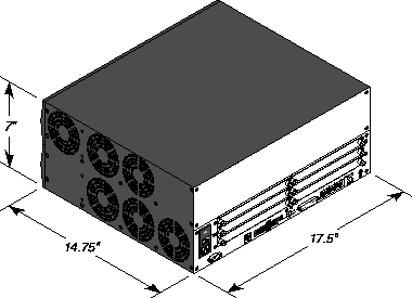
Figure 2-5. Dimensions of the redundant power supply unit
To set up the MAX hardware, follow these steps:
- If you are installing the MAX in a rack, insert the unit in the rack and secure it. See
Figure 2-6.
If you are not rack-mounting the MAX, place it where you can have full access to the front and back panels.
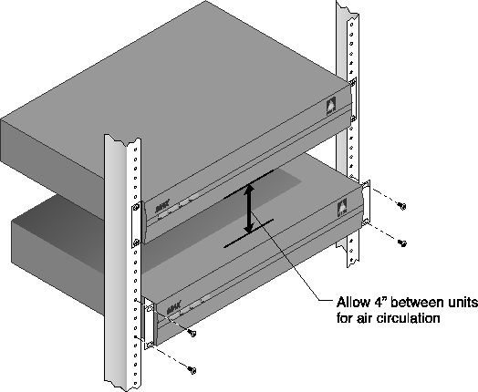
Figure 2-6. Mounting the MAX in a rack
- Connect your VT100 terminal or workstation with VT100 terminal emulation software to
the MAX Control port, using the null-modem cable provided in your package.
- If applicable, connect your hand-held Palmtop terminal to the Palmtop port.
Connecting to input power
- Plug your power cord into your AC or DC power source. (Figure 1-1 and Figure 1-3
display the power sources and Appendix B, "MAX Technical Specifications " lists input
power requirements.)
Connecting to the LAN
To connect to the LAN:
- Connect your Ethernet LAN cable to the Ethernet interface on the MAX.
- The MAX 6000 supplies a 10Base-T Ethernet port. You will need as adapter if you have
another type of Ethernet LAN.
Connecting the MAX to the T1 Line
To connect your MAX to the T1 line:
- Connect the MAX either directly to the T1/PRI line or through other network interface
equipment.
Note: To connect to the demarcation point, where the T1/PRI line's metallic interface
connects to other equipment, the MAX T1/PRI ports must configured to utilize its internal
CSUs. Otherwise, external CSUs or other network (WAN) interface equipment must be
installed between the MAX and the demarcation point.
Enable the internal CSU by setting the Net/T1 > Line Config > Line N > Front End parameter to CSU. Disable the internal CSU by setting Front End to DSX.
- Inform your T1/PRI service provider that your equipment is connected, so they can bring
up the line.
Now that you have connected the MAX, you are ready to learn about the LEDs. Refer to Interpreting the MAX LEDs.
Connecting the MAX to the E1 Line
To connect your MAX to the E1 line:
- Use a cable that is specifically constructed for transmission of E1/PRI signals (CCITT
G700 series recommended).
- The MAX can connect to any DPNSS access point on a Private Branch Exchange (PBX)
or directly to E1 digital services. The MAX can also connect to G.704 framed leased (non-
switching) services for 75 Ohm. (Use cable 2510-0272-001 with 75 Ohm E1 lines.)
When installing the E1 line, the screen of the transmit and receive coaxial cable must be earthed at one end of the line only. Links (jumpers) inside the MAX chassis are provided on the MAX to earth the coaxial screens. The default position of the grounding links on the network line interface, when used with coaxial cable adapter, is on the transmit side (Tx) for 1680 kbps network operations.
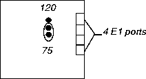
Figure 2-7. One set of links for each E1 port
For a daisy chain connection of the MAX E1/PRI unit, only line 1 needs an earth link (jumper), as line 1 is the only port connected to the telecommunications network.
Connect your MAX to the E1 PRI network interface (TA) equipment supplied by your
PTT.
The maximum distance between the E1/PRI WAN interface equipment and the MAX should not introduce attentuation of more than 6db, when measured at half the maximum data rate (1024 kbps). Also, the cable must have a root F characteristic.
Now that you have connected the MAX, you are ready to learn about the LEDs.
Interpreting the MAX LEDs
Before you start up the MAX, you need to understand the LEDs on the MAX. Figure 2-8 shows the location of LEDs on the front panel, Figure 2-9 shows the location of the LEDs on the redundant MAX front panel and Figure 2-10 shows the Ethernet interface LEDs on the MAX back panel.
Figure 2-8. Location of the MAX LEDs
Table 2-1 lists and describes each LED.
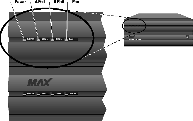
Figure 2-9. Location of the MAX LEDs on the redundant MAX
Table 2-2. Redundant MAX LEDs
LED
|
Description
|
|---|
|
Power
|
This LED is on when the redundant MAX power supply is on.
|
|
A Fail
|
This LED is on only when there is a failure on power supply A, (if one or more of the voltages on the A side has failed: +5, +3.3, +12, -12, -5.)
|
|
B Fail
|
This LED is on only when there is a failure on power supply B, (if one or more of the voltages on the B side has failed: +5, +3.3, +12, -12, -5.)
|
|
Fan
|
This LED is on when the fans are functioning properly (if +12 VDC from either A or B is good.) This LED is off when there is a fan failure.
|
Table 2-2 lists and describes each LED.
MAX back panel
The MAX back panel includes the following LEDs that display the status of the Ethernet interface:
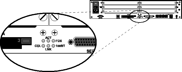
Figure 2-10. Ethernet interface LEDs on MAX back panel
Note: The Classic MAX back panel shows similar LEDs on the Ethernet expansion card if
one is installed. On the Classic MAX, there is one LED for each possible Ethernet interface
(10BaseT, and COAX (10Base2), which are lit when the interface is in use. The ACT and COL
LEDs are the same as those on the MAX 6000 (Table 2-3).
The Ethernet interface LEDs are described in Table 2-3.
Now that you are familiar with the MAX LEDs, you are ready to start up the MAX.
Starting up the MAX
To start up the MAX, follow these steps:
- If you are using a PC, set your terminal emulation package in your communications
software as follows:
- 9600 bps
- 8 data bits
- No parity
- 1 stop bit
- Direct connect
- Position yourself so you can watch the LEDs on the front panel, while you view the
VT100 or Palmtop display.
- Connect one end of the AC power cord to a power source and the other end to the MAX.
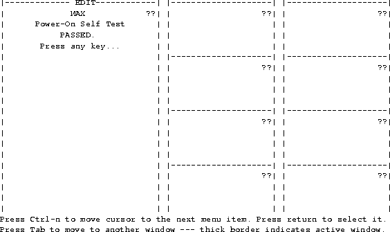
The power-on self-test (POST) starts and finishes within one minute. While the POST is running watch the LEDs, and the VT100 or Palmtop display.
If the Power LED is on and the Fault LED is OFF the MAX is operating properly. You can continue with the next step.
If either LED is incorrect, remove the power cord and do not continue. Contact your Ascend distributor.
Also, notice the VT100 or Palmtop display during the POST. When the POST is successful, this screen appears:
- Press any key. This reminder screen appears, instructing you to edit your line
configuration before you dial:
Edit Line Config
before dialing
Press any key...
Press any key again to display the MAX Main Edit menu as shown.
Main Edit Menu
    >00-000 System
    10-000 Net/T1
    20-000 Host/Dual
    30-000 Ethernet
    40-000 Empty
    50-000 Empty
    60-000 Host/Dual
    70-000 Empty
    80-000 Empty
Continue with Chapter 3, "Quickstart," to get your MAX up and running with a basic configuration.
Continue with Chapter 4, "Navigating the User Interface," to learn how to navigate the MAX user interface before performing more advanced configuration as explained in MAX 6000 Series ISP & Telecommuting Configuration Guide.
![[Top]](../../images/home.jpg)
![[Contents]](../../images/contents.jpg)
![[Prev]](../../images/previous.jpg)
![[Next]](../../images/next.jpg)
![[Last]](../../images/index.jpg)


techpubs@eng.ascend.com
Copyright © 1998, Ascend Communications, Inc. All rights
reserved.


![]() Warning: When installing any equipment, make sure to use proper procedures for static
electricity, such as using a grounding mat and a wrist strap.
Warning: When installing any equipment, make sure to use proper procedures for static
electricity, such as using a grounding mat and a wrist strap.


